
 English
 Español
 عربى
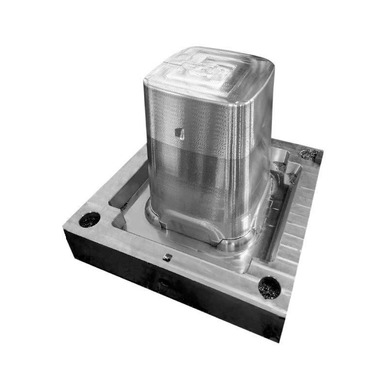
عربىThe Plastic Thin Space Cup Mould represents an innovation in the manufacturing o...
-

+86-15068654601
-

No.62 Zhao Feng Road, Huangyan, Taizhou, Zhejiang, China
+86-15068654601
No.62 Zhao Feng Road, Huangyan, Taizhou, Zhejiang, China
An injection molding machine is a complex assembly of several key systems that work together to convert raw plastic pellets into finished parts. Understanding these components is fundamental to comprehending the machine's operation.
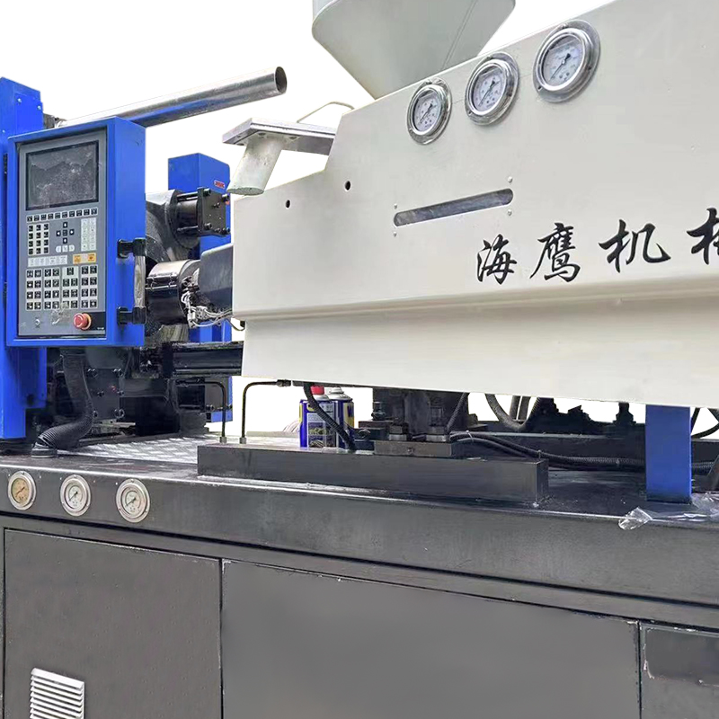
Injection Unit: This is the part of the machine responsible for melting and injecting the plastic. Its main subcomponents include:
Hopper: A large container at the top of the injection unit where plastic granules (and sometimes colorants or additives) are loaded. Gravity feeds the material from the hopper into the barrel.
Barrel: A long, heated cylinder through which the plastic is conveyed. The barrel is equipped with multiple heating zones that gradually melt the plastic as it moves forward.
Reciprocating Screw: A helical screw that rotates inside the barrel. The screw has three primary functions: to convey the solid pellets forward, to melt and mix the plastic through mechanical shearing and contact with the heated barrel, and to act as a plunger during injection. As the screw rotates, it is pushed backward by the accumulating molten plastic at its tip. Once enough material is accumulated, the screw stops rotating and is driven forward hydraulically or electrically, injecting the plastic into the mold.
Nozzle: The component at the end of the barrel that connects to the mold. It forms a sealed connection that allows the molten plastic to flow from the barrel into the mold's runner system and cavities.
Clamping Unit: This unit is responsible for holding the mold closed during injection and opening it for part ejection. It must generate sufficient force to counteract the pressure of the injected plastic, which would otherwise force the mold open. The clamping unit has several key parts:
Stationary Platen: The large front plate to which the fixed half of the mold is attached.
Moving Platen: The rear plate that slides on tie bars (or guide rails) and to which the moving half of the mold is attached.
Tie Bars (or Tie Rods): Heavy steel rods that connect the stationary and moving platens and guide the movement of the moving platen. They also bear the clamping force.
Clamping Mechanism: The system that generates the force to move the moving platen and lock the mold. This can be a hydraulic cylinder (direct clamping), a toggle mechanism (mechanical advantage), or an electric servo motor with a ball screw (all-electric).
Ejector System: A mechanism within the moving platen that pushes the solidified part out of the mold when it opens. This typically consists of ejector pins that are driven forward by an ejector plate.
Control System: The "brain" of the machine. Modern injection molding machines are controlled by a programmable logic controller (PLC) with a user interface (typically a touchscreen). The control system monitors and regulates all machine parameters, including temperatures (barrel zones, mold), pressures (injection, holding, back pressure), speeds (screw rotation, injection, clamping), positions, and times. It stores mold-specific settings for quick changeovers and provides diagnostic information.
Hydraulic or Electric Drive System: The power source for the machine's movements.
Hydraulic Machines: Use hydraulic pumps, valves, and cylinders to power the injection unit, clamping unit, and ejector. They are robust and cost-effective for large machines but consume more energy.
All-Electric Machines: Use servo motors and ball screws for all movements. They offer higher precision, repeatability, and energy efficiency, as motors only draw power when moving. They are quieter and cleaner than hydraulic machines.
Hybrid Machines: Combine hydraulic and electric technologies, often using electric drives for precise functions like injection and a hydraulic system for clamping.
How Does the Injection Molding Process Work, Step by Step?
The injection molding process is a cyclic operation that consists of four primary stages, repeating continuously to produce parts.
Step 1: Clamping: The cycle begins with the clamping unit closing the mold. The moving platen travels forward until the two mold halves make contact, and the clamping mechanism applies full force to lock the mold securely closed. The required clamping force is calculated based on the projected area of the parts and the injection pressure.
Step 2: Injection and Packing: With the mold clamped, the injection unit moves forward so the nozzle contacts the mold's sprue bushing. The screw then acts as a plunger, moving forward at a controlled speed and pressure, forcing the molten plastic through the nozzle and into the mold's runner system and cavities. Once the cavity is nearly full, the machine switches to a holding (packing) pressure. This lower pressure continues to force a small amount of additional plastic into the cavity to compensate for the material shrinkage as it cools and solidifies. The injection and packing stage is critical for part quality, preventing defects like short shots, sink marks, and excessive warpage.
Step 3: Cooling and Plasticizing: After the gate (the small opening into the cavity) freezes off, the holding pressure is no longer needed. The cooling stage begins, during which the plastic inside the mold solidifies as heat is transferred to the mold's cooling channels (which circulate water or oil). Simultaneously, the screw in the injection unit begins to rotate. As it rotates, it conveys new plastic granules forward from the hopper, melting them through mechanical shearing and heat from the barrel heaters. This molten plastic accumulates at the front of the screw, pushing the screw backward. When enough material has accumulated for the next shot, the screw stops rotating. This plasticizing phase occurs concurrently with the cooling of the current part, optimizing cycle time.
Step 4: Ejection: Once the cooling time has elapsed and the part is sufficiently rigid, the clamping unit opens the mold by retracting the moving platen. As the mold opens, the part typically remains on the moving half (attached to the core). The machine's ejector system then activates, pushing ejector pins forward against the part to eject it from the mold. The part falls into a container or onto a conveyor belt. The mold then closes again, and the cycle repeats.
What Are the Main Types of Injection Molding Machines?
Injection molding machines are primarily categorized by the type of drive system they use and by their mechanical configuration. The drive system type has a significant impact on performance, energy consumption, and cost.
Hydraulic Injection Molding Machines: These are the traditional and common type, especially for larger machines. They use hydraulic pumps to generate high pressure and force. Hydraulic machines are known for their robustness, high tonnage capacity, and relatively lower initial purchase price. However, they are less energy-efficient than electric machines because the pump runs continuously. They also require hydraulic oil, which necessitates maintenance and poses a potential fire hazard. They can be noisier and may have slightly less precise control than electric machines.
All-Electric Injection Molding Machines: These machines use servo motors to drive all movements, including screw rotation, injection, clamping, and ejection. They offer several advantages: high energy efficiency (motors only draw power when moving), exceptional precision and repeatability, quieter operation, and cleanliness (no hydraulic oil). They are particularly favored for molding precision parts in cleanroom environments or for applications with tight tolerances. Their initial cost is generally higher than hydraulic machines, but this can be offset by energy savings over time.
The Plastic Thin Space Cup Mould represents an innovation in the manufacturing o...
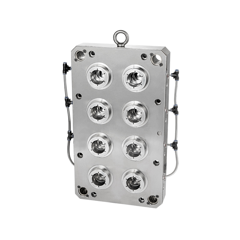
Our Food/Beverage Plastic Crate Mould is meticulously designed to meet the diver...
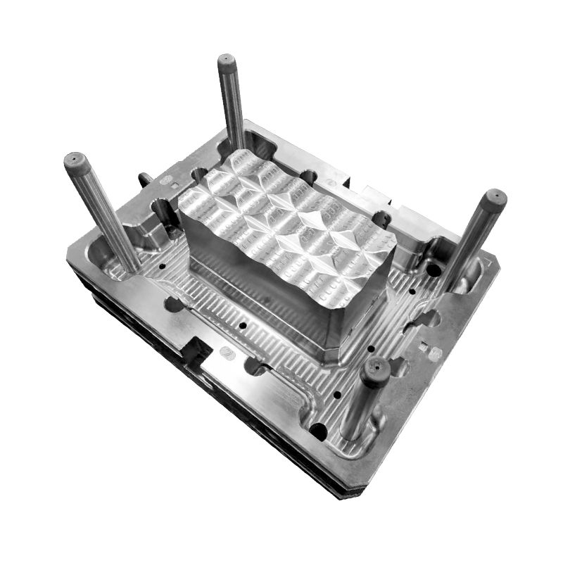
In the realm of plastic furniture storage solutions, our injection mould stands ...
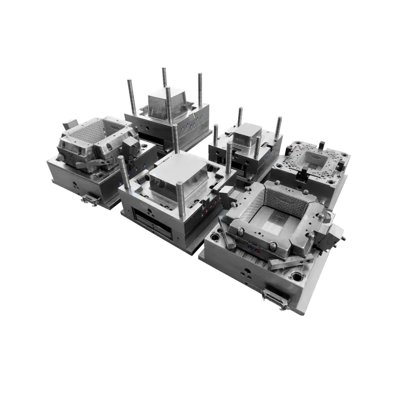
In the realm of contemporary furniture design, the Durable Plastic Rattan Stool ...
Taizhou Huangyan Edge Mould Co., Ltd.
Phone: +86-15068654601
Email: [email protected]
Address: No.62 Zhao Feng Road, Huangyan, Taizhou, Zhejiang, China
Copyright © Taizhou Huangyan Edge Mould Co., Ltd. All Rights Reserved.