
 English
 Español
 عربى
عربىThe Plastic Thin Space Cup Mould represents an innovation in the manufacturing o...

-

+86-15068654601
-

No.62 Zhao Feng Road, Huangyan, Taizhou, Zhejiang, China
+86-15068654601
No.62 Zhao Feng Road, Huangyan, Taizhou, Zhejiang, China
The following bullet points describe the main classifications of moulds designed for in-mould labeling (IML) on food containers with anti-theft features such as tamper-evident hinges or breakable tabs.
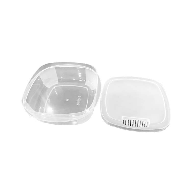
Single-Face IML Mould (Lid Only): Produces only the container lid with an IML label applied to the outer surface. The anti-theft feature consists of a thin bridge (0.3 to 0.5 mm thickness) connecting the lid to a tamper ring. Cavity count ranges from 2 to 8 per mould for lids of 100 mm to 200 mm diameter. Cycle time is 6 to 10 seconds for polypropylene (PP) material.
Single-Face IML Mould (Base Only): Produces only the container base. Anti-theft features include snap-fit ribs that require a tool for opening. The label is applied to the base sidewall or bottom. Cavity depth is 40 mm to 100 mm. This mould type requires ejector pins with extended stroke (80 mm to 120 mm) to release deep containers without label damage.
Stack Mould for Lid and Base (Two-Level): Produces lids and bases simultaneously on two parallel parting lines. The central plate rotates 180 degrees between injections. Cavity configuration is typically 2+2 or 4+4 (lids + bases). Stack moulds reduce machine requirements by 50 percent compared to using two separate moulds. However, mould height is 800 mm to 1,200 mm, requiring injection machines with platen spacing above 1,300 mm.
Unscrewing Mould for Threaded Anti-Theft Closures: The container features a screw cap with a tamper-evident band. The mould incorporates a gear-rack mechanism or hydraulic unscrewing unit. The anti-theft band has 6 to 12 bridges that break upon first opening. Unscrewing stroke is 8 mm to 15 mm. Cycle time is 12 to 18 seconds, 30 to 40 percent longer than non-unscrewing moulds due to the unscrewing movement.
Cavity and Core Materials
The cavity and core components are subjected to injection pressures of 60 to 100 MPa and melt temperatures of 200°C to 260°C (for PP). DIN 1.2343 (X40CrMoV5-1) chromium hot-work steel is standard. Composition includes 0.40% carbon, 5.0% chromium, 1.3% molybdenum, and 0.4% vanadium. Hardness after heat treatment is 48 to 52 HRC. Tensile strength is 1,450 MPa. For production runs exceeding 1 million cycles, DIN 1.2379 (X153CrMoV12) high-carbon chromium steel is used. Hardness reaches 58 to 60 HRC, providing wear resistance against glass-filled PP materials (10 to 30 percent glass fiber). For prototype moulds or runs below 200,000 cycles, P20 steel (DIN 1.2738) pre-hardened to 38-42 HRC is selected. P20 reduces machining time by 20 percent because no post-hardening heat treatment is required.
Label Positioning Components
Electro-permanent magnets are embedded in the cavity wall to hold IML labels before injection. Magnets are neodymium (NdFeB) grade N35 to N45, with nickel-copper-nickel plating. Each cavity contains 8 to 16 magnets of 3 mm to 6 mm diameter. The magnetic pull force per magnet is 0.5 to 1.5 N. For non-ferrous labels, vacuum ports (0.5 mm to 1.0 mm diameter) replace magnets. Vacuum channel material is stainless steel 30. Vacuum pressure is -0.08 to -0.09 MPa. The label alignment frame is machined from aluminum alloy 6061-TFrame surfaces in contact with the label have a surface finish of Ra 0.2 microns to avoid label tearing during placement.
Anti-Theft Feature Inserts
The tamper-evident bridges and weakening lines are molded using separate inserts. The insert material is DIN 1.2767 (X45NiCrMo4) nickel-chromium-molybdenum steel. Hardness is 52 to 54 HRC. The inserts have sharp corner radii of 0.05 mm to 0.10 mm to produce clean break lines. For high-cycled moulds (over 500,000 cycles), the inserts are coated with titanium carbonitride (TiCN) by physical vapor deposition (PVD). Coating thickness is 2 to 4 microns. Coated inserts show 50 percent less wear compared to uncoated inserts, maintaining bridge thickness tolerance of ±0.02 mm.
Cooling System Materials
Cooling channel baffles and bubblers are made of copper alloy CuZn39Pb3 (C38500). Thermal conductivity is 110 W/m·K, compared to 24 W/m·K for steel. Baffle diameter is 6 mm to 12 mm. O-rings sealing the cooling circuits are fluorocarbon rubber (FKM, Viton) with a temperature rating of -20°C to 200°C. For moulds running at cycle times below 5 seconds, conformal cooling channels are produced by laser powder bed fusion (3D printing) using maraging steel 1.2709. Conformal channels follow the cavity contour within 3 mm to 5 mm distance, reducing cooling time by 30 to 40 percent compared to drilled channels.
The following precautions are represented by special symbols to guide safe and efficient operation.
Label Placement Verification — Before closing the mould, verify that each label sits flat against the cavity surface. A lifted label corner (detectable by visual inspection or through a side window) will become wrinkled during injection, producing a reject part. Use a vacuum gauge to confirm holding force: minimum -0.05 MPa for vacuum-held labels. For magnet-held labels, check that the label covers all magnets. Missing magnets (detectable by a label not adhering) indicate magnet breakage from previous collisions with the label picker.
Melt Temperature Control — For PP-based IML, maintain melt temperature at 220°C to 250°C. Temperatures below 200°C produce incomplete label adhesion because the polymer does not flow through the label mesh (labels have 30-50% open area). Temperatures above 260°C degrade the label's adhesive layer (typically maleic anhydride grafted PP), reducing bond strength by 40 to 60 percent as measured by 180-degree peel test (should exceed 5 N/25mm). Install a melt thermocouple in the nozzle body, not in the barrel, because label adhesion is sensitive to temperature at the point of injection.
Injection Speed Profile — Use a three-stage speed profile: (1) slow at 15-30 mm/s for the first 5-10% of fill to wet the label without displacing it, (2) medium at 40-60 mm/s for the main filling to 90% of cavity volume, (3) slow at 20-35 mm/s for final pack to avoid flash at the anti-theft bridge features. Exceeding 80 mm/s at any stage causes label displacement, visible as a 0.5-2.0 mm shift of the label relative to the container edge. Measure label position on the first 50 parts using an optical comparator; reject any shift exceeding ±0.3 mm.
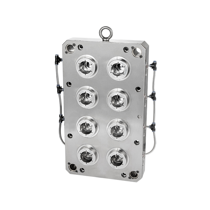
The Plastic Thin Space Cup Mould represents an innovation in the manufacturing o...
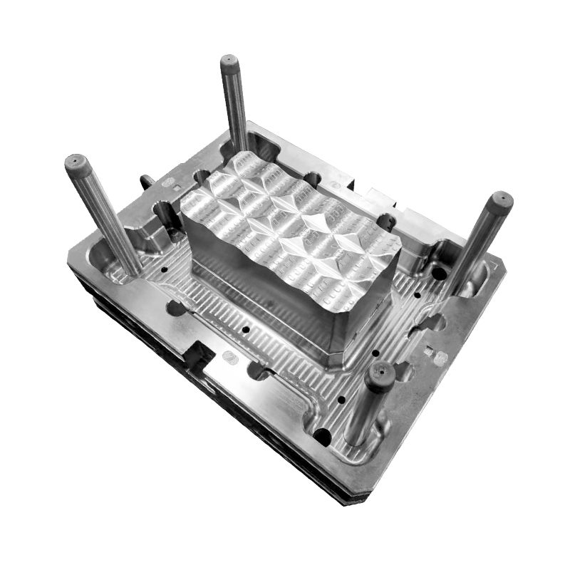
Our Food/Beverage Plastic Crate Mould is meticulously designed to meet the diver...
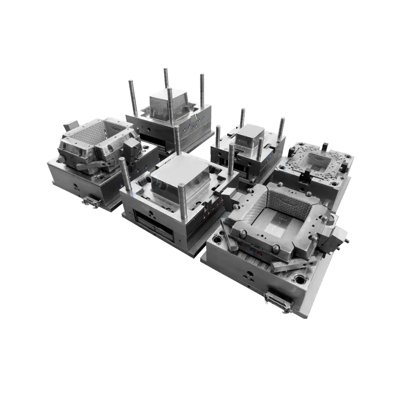
In the realm of plastic furniture storage solutions, our injection mould stands ...
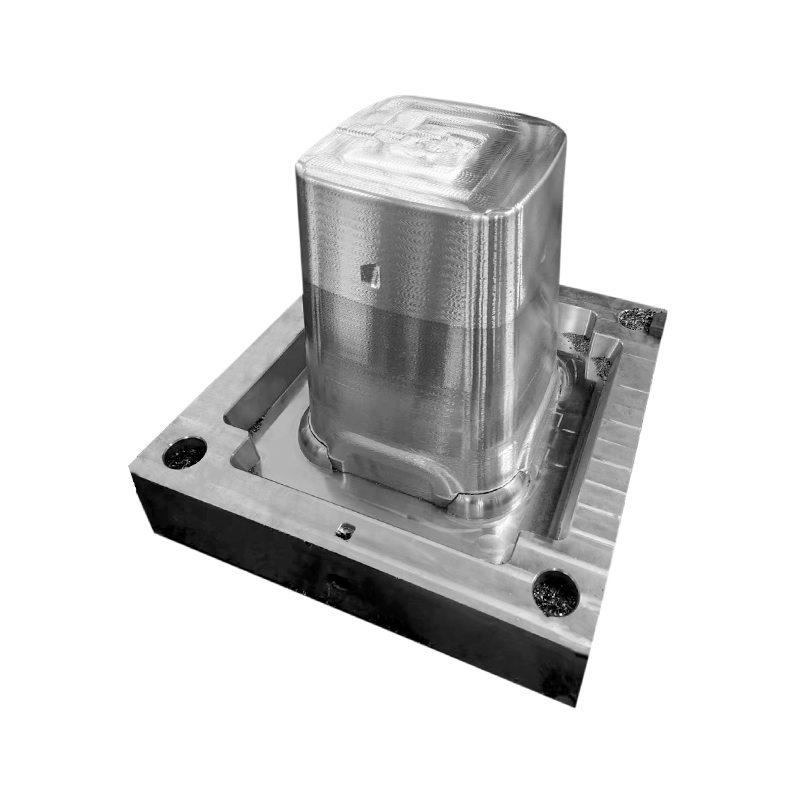
In the realm of contemporary furniture design, the Durable Plastic Rattan Stool ...
Taizhou Huangyan Edge Mould Co., Ltd.
Phone: +86-15068654601
Email: [email protected]
Address: No.62 Zhao Feng Road, Huangyan, Taizhou, Zhejiang, China
Copyright © Taizhou Huangyan Edge Mould Co., Ltd. All Rights Reserved.
