
 English
 Español
 عربى
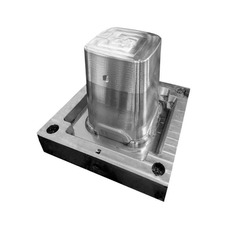
عربىThe Plastic Thin Space Cup Mould represents an innovation in the manufacturing o...
-

+86-15068654601
-

No.62 Zhao Feng Road, Huangyan, Taizhou, Zhejiang, China
+86-15068654601
No.62 Zhao Feng Road, Huangyan, Taizhou, Zhejiang, China
Cavity numbering and arrangement patterns for cutlery.
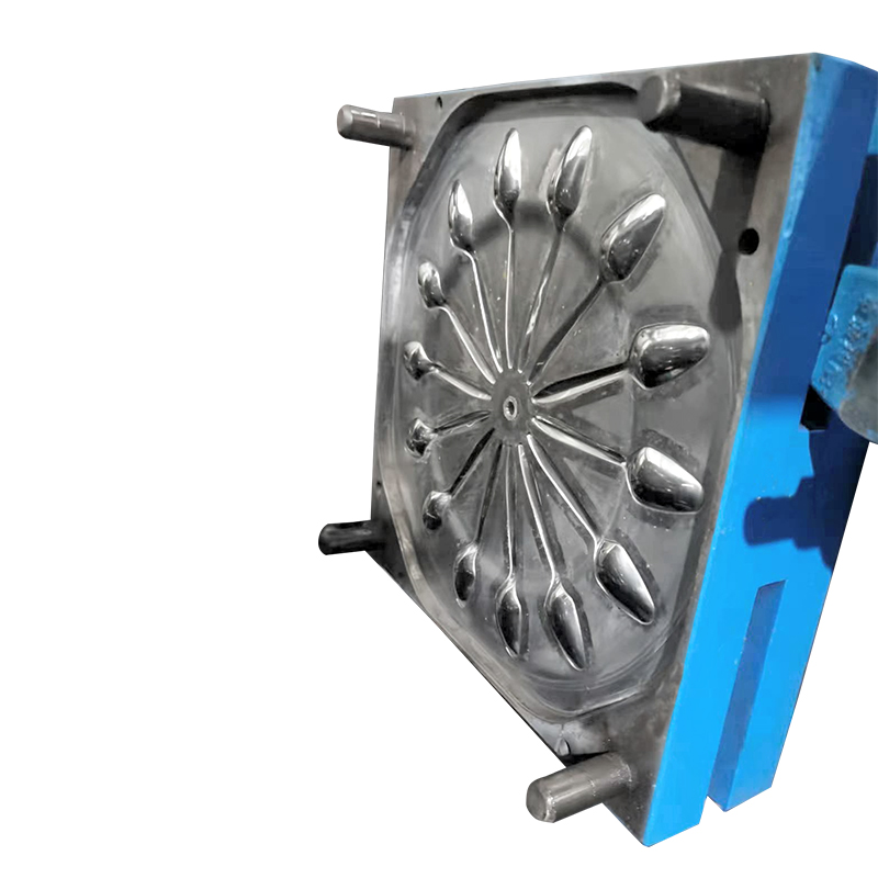
Multi-cavity cutlery moulds produce multiple forks, knives, or spoons in a single injection cycle. Cavity counts typically range from 8 to 64, depending on part size and machine clamping force. A spoon of 150 mm length requires 10–15 cm² projected area. A 48-cavity mould for such spoons has a total projected area of 480–720 cm², requiring a clamping force of 250–450 tonnes (calculated at 0.5–0.7 tonnes/cm² for polypropylene). Cavity arrangement follows two patterns. Linear arrangements place cavities in 2–4 rows along the mould length, suited for cutlery with straight profiles. Radial or star arrangements place cavities around a central sprue, reducing flow distance variation between cavities but complicating ejection. The distance between adjacent cavities is maintained at 35–50 mm to allow cooling channel placement. Moulds with cavity spacing below 35 mm show temperature variation of 8–12°C across the mould face, causing uneven filling.
Runner system design for uniform filling.
All cavities in a multi-cavity mould must fill at nearly the same time and pressure. A balanced runner system achieves fill time variation below 0.1 seconds between the first and last cavity. For cutlery moulds, runner cross-sections are trapezoidal or full-round. Round runners (diameter 4–8 mm) offer lower pressure drop but require machining in both mould halves, increasing cost. Trapezoidal runners (base width 6–10 mm, depth 3–5 mm) are machined into one half only. The runner length from sprue to each cavity is kept equal; if geometric symmetry is impossible, runner diameters are adjusted. A cavity 50 mm farther from the sprue receives a runner diameter 0.5–1.0 mm larger to compensate. Computer flow simulation (Moldflow or similar) predicts fill imbalance. For a balanced 32-cavity spoon mould, flow simulation shows cavity pressure variation of 2–5% across all cavities. An unbalanced mould may show 15–25% pressure variation, resulting in short shots in some cavities and flash in others.
Gate type and location for thin cutlery profiles.
Cutlery parts have thicknesses of 1.5–3.0 mm at the handle and 0.5–1.5 mm at the bowl or tines. The gate—where molten plastic enters the cavity—must be positioned to avoid flow-induced stress in thin sections. Common gate types for multi-cavity cutlery moulds include edge gates (2–4 mm width, 0.8–1.5 mm thickness) located at the handle end, and fan gates (6–12 mm width, tapering to 0.5–1.0 mm) for spoons with broad bowls. Tunnel gates (submarine gates) are used for automatic degating; the gate shears as the mould opens, eliminating a separate trimming step. A tunnel gate requires a 0.8–1.2 mm diameter opening angled at 30–45 degrees. The gate location must avoid the tine area of forks (where thickness drops to 0.5–0.8 mm) because shear heating at the gate can raise melt temperature by 15–30°C locally, causing burn marks. In a 48-cavity fork mould, gate placement at the handle end 10–15 mm from the fork neck produces acceptable flow. Placing the gate closer than 8 mm to the tines increases reject rates from 2% to 8–12%.
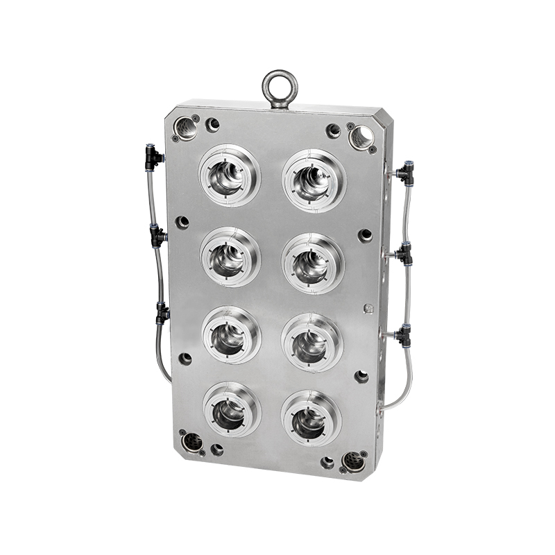
Ejection system for high-cavity count cutlery moulds.
Multi-cavity cutlery moulds require ejection systems that remove all parts simultaneously without distortion. Ejection methods include stripper plates, ejector pins, and air blast. Stripper plates (a moving plate that pushes the parts off the core) are preferred for thin cutlery because they distribute ejection force evenly. A stripper plate engages the cutlery at the handle perimeter (2–3 mm contact width). Ejector pins (1.5–3.0 mm diameter) are used when the part geometry prevents a stripper plate. For a 64-cavity knife mould, 64 to 128 ejector pins are arranged in rows. Ejector pin return must be positively controlled; spring return is unreliable above 32 cavities. Hydraulic or pneumatic ejector plates with stroke limiters (10–20 mm stroke) are standard. Air ejection (0.4–0.6 MPa compressed air applied through core vents) assists the release of parts with deep contours. A combination of stripper plate and air ejection reduces cycle time by 0.5–1.0 seconds compared to ejector pins alone because pins leave witness marks that require post-processing for some cutlery grades. For medical or food-contact cutlery, witness marks from ejector pins are acceptable as long as surface roughness remains below Ra 0.8 µm.
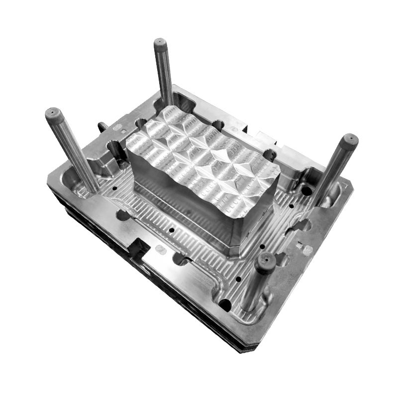
Cycle time breakdown for high-cavity moulds.
A multi-cavity cutlery mould operating on an injection moulding machine follows a repeating cycle of five phases. For a 48-cavity polypropylene spoon mould, typical timings are: mould closing (0.5–1.0 seconds), injection (1.5–3.0 seconds depending on shot weight—200–500 grams for 48 spoons), holding pressure (1.0–2.0 seconds), cooling (6–12 seconds—the dominant phase), and mould opening/ejection (0.5–1.5 seconds). Total cycle time ranges from 9.5 to 19.5 seconds. At the lower end (9.5 seconds), output is 48 spoons × 360 cycles per hour = 17,280 spoons per hour. At the upper end (19.5 seconds), output is 8,860 spoons per hour. The cooling phase occupies 60–70% of the total cycle. Reducing cooling time by 2 seconds increases output by approximately 20% for a 10-second baseline. Cooling time is determined by part wall thickness; a 2.0 mm handle requires 8–10 seconds of cooling; a 1.0 mm bowl requires 4–6 seconds. The thickest section dictates the minimum cooling time.
Part-to-part consistency measurement.
Multi-cavity moulds inevitably produce slight variations between cavities due to differences in venting, cooling, and flow resistance. Quality control measures these variations through systematic sampling. A standard protocol requires taking one part from each cavity every 4–8 hours of production. These 48 parts (for a 48-cavity mould) are weighed individually. For polypropylene spoons of 200 mm length and 2.0 mm maximum thickness, acceptable cavity-to-cavity weight variation is ±1.5% from the mean. A mould producing parts with a weight variation above ±2.5% requires investigation. Common causes of variation include: blocked vents in specific cavities (a 0.01 mm vent clogged with plastic residue increases fill resistance by 20–30%), cooling channel blockage (a 1°C higher cavity temperature reduces weight by 0.2–0.5%), or a damaged gate (gate erosion increases diameter by 0.2 mm, increasing fill rate and part weight by 1–2%). After repair, the mould should return to ±1.5% variation. A mould exceeding ±3.0% variation typically shows a 5–10% higher scrap rate because parts from low-weight cavities are incomplete, and parts from high-weight cavities have flash.
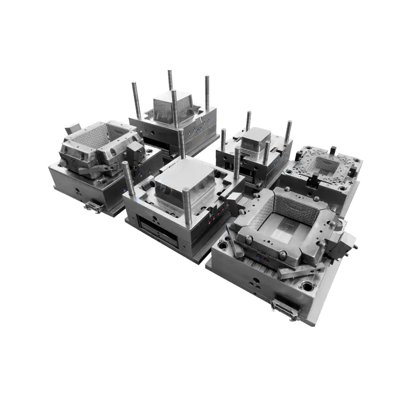
Wear management in high-cavity cutlery moulds.
Multi-cavity moulds produce millions of cycles before replacement. A typical mould for disposable cutlery is designed for 5–10 million cycles. Wear occurs at four locations. The gate area experiences erosion from high-velocity melt (200–600 m/s at the gate restriction). After 2–3 million cycles, gate dimensions increase by 0.1–0.2 mm, increasing part weight by 2–5% in affected cavities. Gate bushings made of tool steel (hardness 58–62 HRC) or tungsten carbide extend gate life to 5–8 million cycles. The parting line (where mould halves meet) wears due to clamping force and plastic flash. A 0.03 mm wear at the parting line reduces clamping effectiveness, allowing flash to form. Parting line surfaces are nitrided (0.05–0.10 mm depth, 60–65 HRC surface hardness) to resist wear. After 4 million cycles, regrinding the parting line restores flatness to within 0.01 mm over the mould face. Core and cavity surfaces for cutlery—particularly fork tines and spoon bowls—require polishing after 3–5 million cycles because surface roughness increases from Ra 0.1 µm to Ra 0.4–0.6 µm, causing parts to stick. Ejector pins wear at the pin head and guide bore; pin replacement every 2 million cycles is recommended. A mould with proper wear management maintains reject rates below 2% throughout its 8–10 year service life.
The Plastic Thin Space Cup Mould represents an innovation in the manufacturing o...
Our Food/Beverage Plastic Crate Mould is meticulously designed to meet the diver...
In the realm of plastic furniture storage solutions, our injection mould stands ...
In the realm of contemporary furniture design, the Durable Plastic Rattan Stool ...
Taizhou Huangyan Edge Mould Co., Ltd.
Phone: +86-15068654601
Email: [email protected]
Address: No.62 Zhao Feng Road, Huangyan, Taizhou, Zhejiang, China
Copyright © Taizhou Huangyan Edge Mould Co., Ltd. All Rights Reserved.