
 English
 Español
 عربى
عربىThe Plastic Thin Space Cup Mould represents an innovation in the manufacturing o...
-

+86-15068654601
-

No.62 Zhao Feng Road, Huangyan, Taizhou, Zhejiang, China
+86-15068654601
No.62 Zhao Feng Road, Huangyan, Taizhou, Zhejiang, China
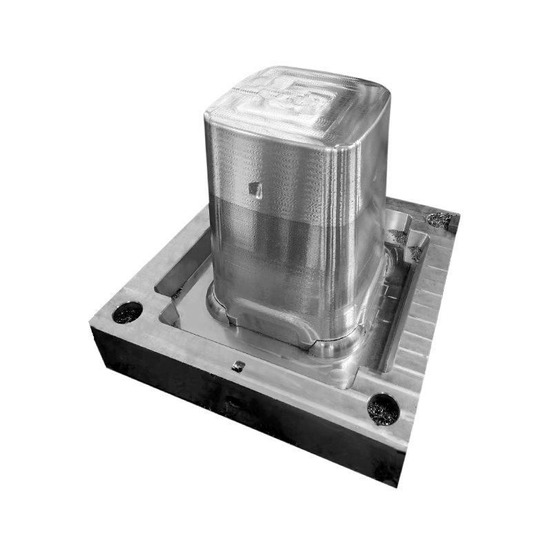
Cycle times that drag longer than they should, cavities producing parts at inconsistent weights, cooling that becomes the bottleneck before anything else gets a chance to — these are the production frustrations that plastic pail and bucket manufacturers run into when the tooling is not matched to the output target. The mould is not just the tool that makes the part. It sets the ceiling on what the production line can actually achieve, and that ceiling is either working for you or against you on every shift. A Pail Bucket Mould designed with efficiency as a real objective changes that picture, and understanding where the gains actually come from is what separates a well-informed tooling investment from an expensive guess.
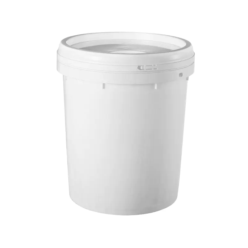
A Pail Bucket Mould is the steel tooling used in injection moulding to form plastic pails and containers. Molten plastic enters the cavity under pressure, solidifies in the shape of the tool, and is ejected as a finished part. Then the mould closes and the whole thing happens again.
The injection moulding machine provides the force and the heat. But the mould decides how that energy gets used and how fast the process can turn around each cycle. Two factories running the same machine with different moulds can produce very different output volumes — and the gap is not a mystery once you understand what the mould controls.
What a well-designed mould determines:
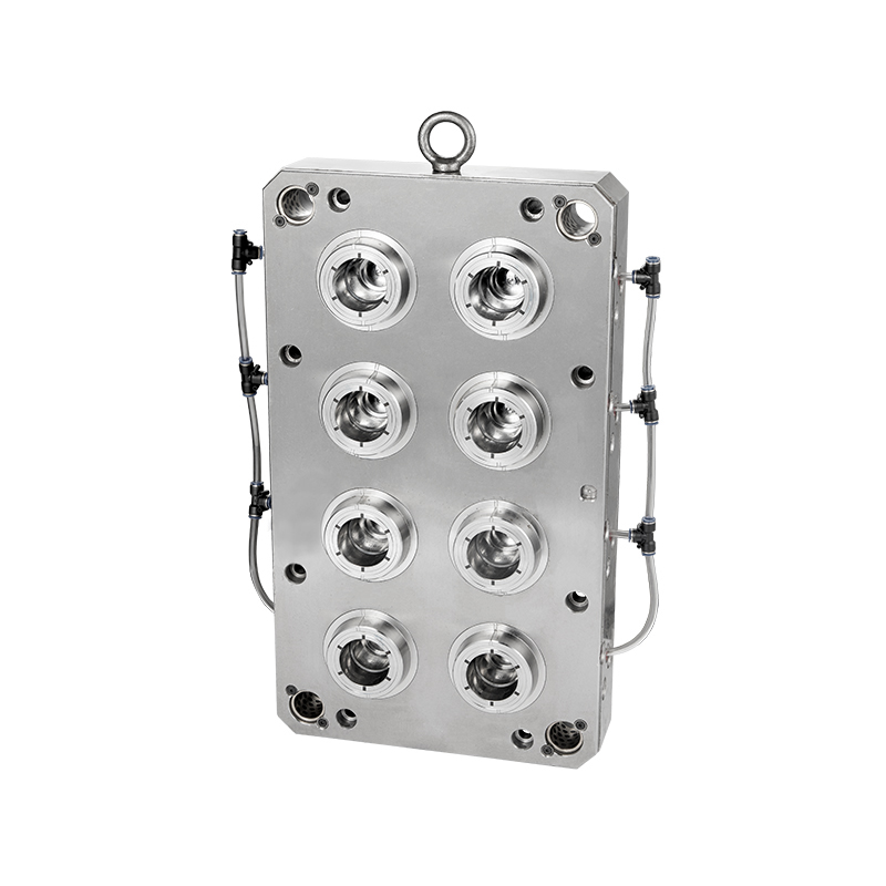
A single-cavity mould makes one pail per cycle. A two-cavity mould makes two. A four-cavity mould makes four — all from the same injection, the same cooling period, and the same ejection sequence. As long as the machine has enough clamping force and injection volume to fill everything cleanly, multi-cavity tooling multiplies output without multiplying cycle time.
This is one of the most direct levers available in pail production. The tooling investment is higher, but it gets recovered through more parts per hour, lower labor cost per unit, and lower energy cost per part. The math tends to work out clearly in high-volume environments.
That said, multi-cavity tooling is not infinitely scalable. The practical limits come from clamping force capacity, injection volume, cooling system load, and the physical size of the mould against the machine's platen. For large-format pails, two or four cavities is a common production configuration. For smaller containers, higher counts are achievable on appropriately sized machines.
In injection moulding of products like pails and buckets — which have meaningful wall thickness — cooling typically accounts for a large portion of the total cycle. The plastic arrives at high temperature and has to solidify before it can be ejected cleanly. If the cooling system is inadequate or uneven, the part either warps after it leaves the mould or has to sit in the tool longer than necessary.
The network of water channels running through the mould is what pulls that heat out. How those channels are laid out determines how quickly — and how evenly — cooling happens.
Channels that closely follow the shape of the cavity surface pull heat out more evenly than straight-drilled channels running at a distance from the critical areas. For pail moulds with curved walls and varying thickness, good cooling coverage across the full cavity surface produces more consistent results.
When the cooling is working well:
None of this requires a more powerful machine. It requires a better-designed mould.
In a cold runner mould, the plastic that fills the channels connecting the injection point to the cavities solidifies with each shot. That solidified runner gets ejected along with the part — as material that either gets thrown away or recycled. It represents both material cost and extra cycle steps.
A hot runner system keeps those channels at melt temperature throughout the run. Nothing solidifies in the runner, so there is nothing to eject, separate, or recycle. Each shot goes directly into the cavities.
For high-volume pail production, the efficiency case for hot runners is usually straightforward. Runner material adds up over millions of cycles. Cycle time reductions from eliminating runner ejection and separation steps compound over every shift. Fill pressure and temperature also stay more consistent across cavities, which supports part quality.
The trade-off is a higher mould cost and more complexity in temperature control. Whether the investment pays back depends on volume, material cost, and the relative value of cycle time reduction for that specific operation.
| Design Factor | How It Affects Efficiency | What Happens When It Is Poorly Done |
|---|---|---|
| Cavity count | Sets parts per cycle | Low output relative to machine capacity |
| Cooling channel layout | Controls cooling time and uniformity | Long cycles, warping, dimensional variation |
| Runner system type | Affects material waste and cycle steps | Runner waste, inconsistent fill, extra steps |
| Gate location and design | Controls fill balance and surface finish | Weld lines, short shots, surface defects |
| Ejection system design | Determines release speed and cleanliness | Slow ejection, part damage, extended cycles |
| Steel grade and hardness | Affects dimensional stability over time | Premature wear, cavity drift, quality issues |
| Mould base alignment | Controls part-to-part consistency | Flash, dimensional drift, downstream problems |
After cooling, the mould opens and the part has to leave the cavity cleanly. For pails — which have deep walls even with generous draft — reliable ejection without deforming the part requires a system matched to the geometry.
Stripper plates, ejector pins, and air-assisted ejection are the common approaches, and for pails, air assistance that breaks the vacuum between the part and the core is frequently used. When ejection sticks, marks the part, or forces the cycle to pause while the part clears, that time loss accumulates quickly across a shift.
An ejection system designed carefully for the specific part geometry does two things at once: it keeps cycle time tight and it keeps the reject rate down. Both matter to the production economics.
The steel used for the cavity and core components determines how well the mould holds its dimensions over time. As the tool cycles through injection pressure, heat, and ejection forces millions of times, softer or lower-grade steel wears at the cavity surfaces, gate areas, and parting lines.
That wear is slow at first and easy to ignore. Then the parts start drifting dimensionally. Flash appears at the parting line. Quality interventions become more frequent. Eventually, cavity replacement causes a significant production interruption.
Higher-grade tool steel, properly hardened and surface-finished, holds its dimensions across a longer service life. The additional mould cost is recovered through fewer quality problems, less unplanned downtime, and a longer interval before major maintenance becomes necessary.
A pail mould running in an automated cell — with consistent injection parameters, automated part removal, and in-line checks — produces more uniform output than a manually attended line. Operator variation between cycles, handling inconsistencies, and timing differences all introduce variability that automation removes.
Beyond the obvious labor saving, there are practical efficiency benefits that are easy to underestimate:
For mould design to support automation effectively, the part exit geometry, cycle timing, and ejection consistency need to be part of the specification from the start — not retrofitted after the tool is already built.
Before the mould order is placed, a few practical questions tend to reveal whether the proposed tool will actually deliver the production performance needed:
Suppliers who answer these questions specifically and with documentation behind the answers are in a different category from those who respond in generalities.
Production efficiency in plastic pail manufacturing is built into the mould before the first part ever runs. Cavity count sets the output multiplier. Cooling design sets the minimum cycle time. The runner system determines material yield. Steel grade determines how long the tool holds its performance. Each of these is a decision made during mould specification, and each one has a direct effect on what the production line delivers day after day. Taizhou Huangyan Edge Mould Co., Ltd. manufactures Pail Bucket Mould tooling for plastic container production, working with manufacturers on cavity configuration, cooling design, material selection, and production volume requirements. If you are planning a new pail production line or reviewing tooling options for an existing operation, reaching out to their technical team is a practical next step.
The Plastic Thin Space Cup Mould represents an innovation in the manufacturing o...
Our Food/Beverage Plastic Crate Mould is meticulously designed to meet the diver...
In the realm of plastic furniture storage solutions, our injection mould stands ...
In the realm of contemporary furniture design, the Durable Plastic Rattan Stool ...
Taizhou Huangyan Edge Mould Co., Ltd.
Phone: +86-15068654601
Email: [email protected]
Address: No.62 Zhao Feng Road, Huangyan, Taizhou, Zhejiang, China
Copyright © Taizhou Huangyan Edge Mould Co., Ltd. All Rights Reserved.